W1REX QRP Transmitter
in
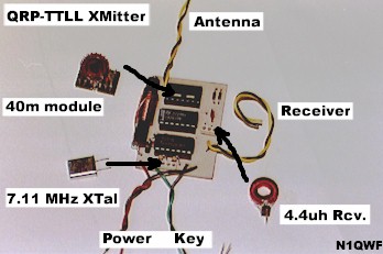
This is a 40/80M Amateur Band CW (continuous wave) transmitter built from parts and board provided by Rex Harper (W1REX). It was a preparation for a QRPme club project.
Introduction
 This is a simple 40 or 80 meter CW transmitter based on an article by Phil Anderson, W0XI that appeared in the October 1981 issue of CQ Magazine. It has been adapted, modified, and laid out on foil by Rex Harper, W1REX. These instructions and the second beta unit were built by myself, Stephen Houser N1QWF. Doug DeMaw, W1FB also spouts a version in one of his QRP design books and attributes it to the G-QRP club. The transmitter is designed around two digital logic chips, the 7400 NAND gate (IC1) for the oscillator, and the 7403 open-collector NAND gate (IC2) for the final amplifier stage. Because the circuit uses digital logic gates for a purpose they were not quite designed for, the maximum useable frequency is probably around 30 meters. We are planning to build a 30 meter or higher version for testing these limits.
Circuit Description
The main oscillator uses the two of the 7400's NAND gates (IC1) with feedback through a crystal (X1). For the 80 meter version, a 3.579 MHz colorburst crystal is readily available. A variable capacitor could be added in series with the crystal to rubber the oscillating frequency a few kHz and gain a small selection of transmitting frequency. The output of the oscillator is fed into another of the 7400's NAND gates (IC1) for buffering and isolation from the rest of the transmitter (out to pin 8 ). The crystal is installed in part of a DIP socket, making it easily removable for switching operating frequencies.
The keyer consists of the last of four NAND gates in the 7400 chip( IC1). When the key is open, the input to the gate is high and the output low (disabling the output of the finals). When the key is closed, the input is grounded (low) and the output is high (enabling the output of the finals).
The final amplifier consists of all four of the 7403's NAND gates (IC2) connected in parallel. When the key is closed, the output of these gates effectively follow the input from the oscillator (inverted), buffering and amplifying it out to pins 3, 6, 8, and 11, which are all tied together as the output of the finals.
The output pi network filter circuit consists of C1, C2, C3, and L2. All of which are installed on a DIP header that can be easily removed and replaced on the circuit board. The network provides approximately 50 Ohm impedance for the antenna.
Full break-in keying is provided through two back-to-back diodes (D2 and D3), the 47pf capacitor C4, and the coil L1. The diodes ensure the receiver sees a maximum of 0.6 volts during transmission. The break-in circuit adds little load to the output pi-network and antenna because C4 is small and effectively shunted to ground by diodes D2 and D3. L1 should be tuned to eliminate the capacitive reactance of C4 so the receiver matches the antenna. L1, similar to the X1 crystal, is installed in part of a DIP socket for easy band hopping.
Power to the circuit is provided by a 6 volt DC supply. The supply is fed through diode D1 (a 1N4004 or 1N4001) which drops approximately 1.0 volts, resulting in about 5.0 volts for the circuit operation. If you want to supply the circuit with 12 volts DC, you will need to construct a voltage divider circuit that provides the appropriate 5.0 volt supply
Construction
Construction is very simple. Our versions made generous use of DIP sockets for the two TTL chips and the removable output network (which is tuned for each band). In addition, a DIP socket was scavenged and chopped apart to provide two 3-pin sockets. One 3-pin socket was used for the oscillator's crystal, the other for the receiver coil, which are also removable for easy band hopping. RCA phono plugs and jacks seem to be the easiest connectors to use for the antenna, key, receiver, and power connections. Substitute your own, or connect directly to your outside components.
If you want to wind your own torrid coils, go for it. I wound my own and have had good results with them. I used T50-2 coils for all the coils on both 80 and 40 meters. The 40 uH coil is rather tough. Trying to get 90 turns onto a half-inch core is not easy, I reverted to using 30 gauge wire. The number of windings needed with 28 gauge wire is given in the parts list.
Step-by-Step
Perhaps the easiest way to construct the QRP TTLL transmitter is following these simple step-by-step directions.
- Choose either the 80 or 40 meter version and collect up all the appropriate parts.
- Clean up your circuit board, with steel wool or another mild abrasive so you get good solder connections.
- Install the three DIP sockets first, they occupy the most space and typically have short hard-to maneuver leads. Make sure you orient them so that pin 1 is in the correct position, towards where the RFC coil will be installed.
- Install R1 and R2 next to the DIP socket for the 7400, the need to be mounted vertically.
- If you choose to use partial DIP sockets for the receiver coil and the crystal, now is a good time to break up a socket into (at least) 2, 3-pin sockets. Clip off the center pin and install by soldering the outer two pins of one socket in the crystal location, and the other in the location for coil L1.
- Proceed to install the other fixed components on the board, D1, D2, D3, R3, and C4. Install the RFC coil on the board last. It may not lie all the way on the board as it is a little bulky.
- Attach phono plugs to some short leads and attach one to the power (+,G) connections, one to the antenna (A,G) connections, one to the key (K, G) connections, and one to the receiver (R, G) connections.
- Install the 7400 and 7403 IC's in their appropriate sockets. Again be careful to orient them such that pin 1 is in the right location (towards the RFD coil).
You are done with the board! Now you can move on to the plug-in module.
- Use a heat sink when soldering to a DIP header, they will melt.
- Install the capacitors C1, C2, and C3 first leaving room for the coil.
- Install the coil, and perhaps hot-glue it in place if you would your own to keep it from breaking off. Make sure you install the coil on the correct side of the DIP header, the one that would be pins 1 through 7.
Testing and Use
Now the fun begins, select your band module, plug it in, then the receiver coil and the appropriate crystal. Connect your 50 Ohm dummy load and a straight key. To test you can use a separate receiver. Tune your receiver to the crystal frequency and apply power to the transmitter. You should hear the oscillator loud and clear, key the transmitter a few times to ensure you can hear a change in the tone. You should tune a few kHz off the crystal frequency to get a nice sounding note.
If something is not working, disconnect the power. Double check your solder connections and IC orientation. Try applying power and check that the IC's are getting about 5.4 volts DC. If you have a scope or frequency counter available, check the output of the oscillator, then check the output of the finals while keying for a signal that matches the crystal frequency.
After you test everything out on a dummy load, connect your 50 Ohm antenna, or antenna tuner, etc. and you are ready to roll.
I have found the circuit performs nicely on 80 meters. Output on 40 meters is not as good as I would like, perhaps a little fine tuning of my wound coils is in order.
Diagrams
- Schematic Diagram
- Foil Pattern
- Parts Placement
- Construction Photos
Parts List
| Part | Value | Notes |
|---|---|---|
| Components Common to All Versions | ||
| R1, R2 | 390 ohm | |
| R3 | 1 K-ohm | |
| D1 | 1N4004 or 1N4001 | |
| D2, D3 | 1N914 | |
| C1 | 0.01 µF | output coupling |
| C4 | 47 pF | |
| RFC | 100 µH | Radio Shack |
| IC1 | SN7400 | Quad NAND |
| IC2 | SN7403 | Quad NAND (open-collector) |
| 80 Meter Components | ||
| X1 | 3.579 MHz | TV Colorburst Crystal |
| L1 | 40 µH | receiver, 90 turns on T50-2 |
| L2 | 2.2 µH | output, 21 turns on T50-2 |
| C2, C3 | 0.001 µF | output |
| 40 Meter Components | ||
| X1 | 7.110 MHz | |
| L1 | 8.2 µH | receiver, 41 turns on T50-2 |
| L2 | 1 µH | output, 14 turns on T50-2 |
| C2, C3 | 820 pF | output |