MiniPin - Virtal Pinball
in
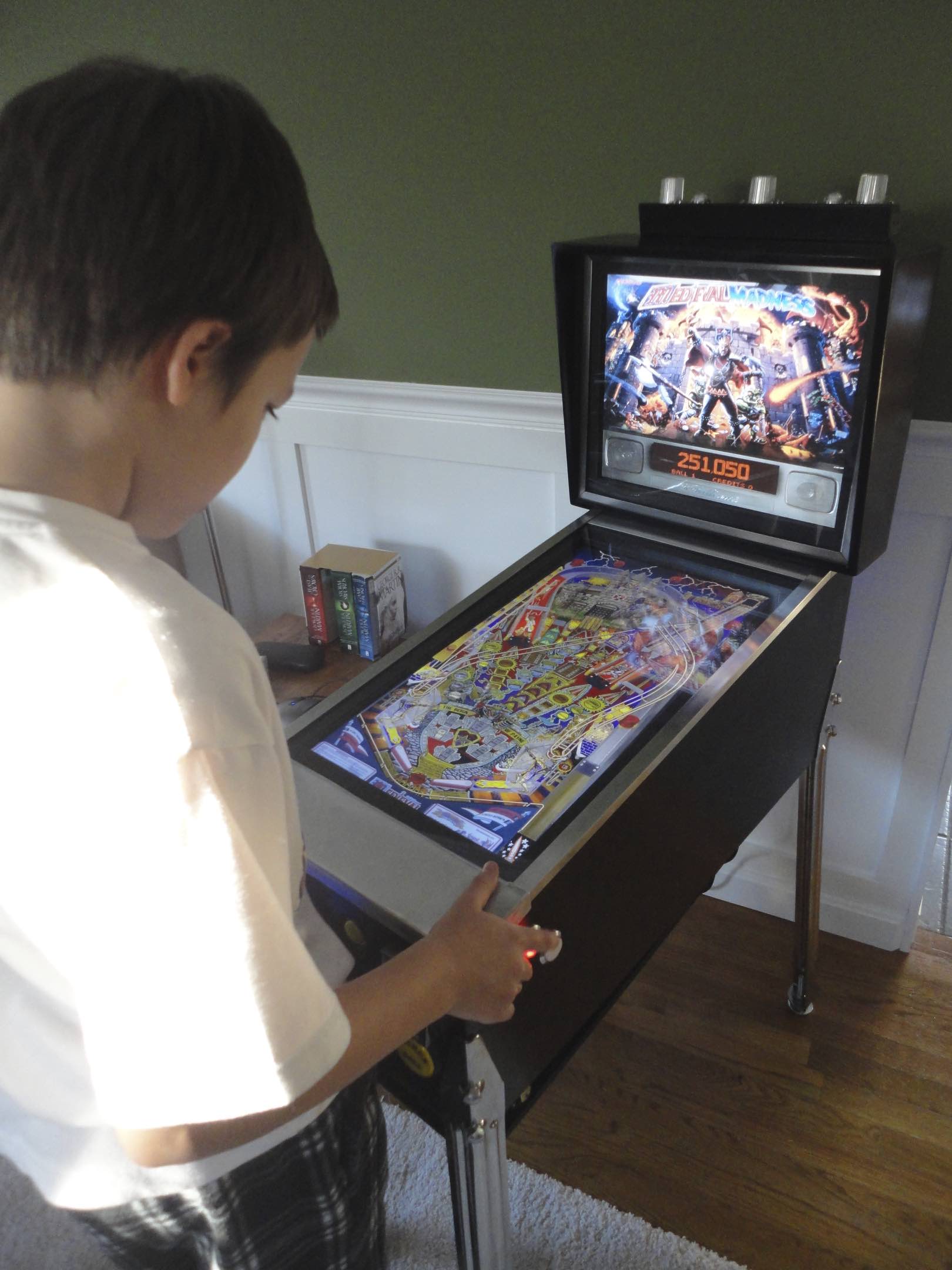
It was August 28, 2011 when I first made a mockup of a virtual pinball machine that came to be known as ‘MiniPin’. The virtual pinball feever had started a few days earler when a friend saw the Kids Mame 1 build on my website and said, innocently, “…you should build a virtual pin cabinet.”. Of course, that’s exactly what I did.
Overview
For me the most enjoyable thing about a virtual pinball cabinet was clearly the building process. I just like building things and the project really involved a wide array of things that needed to be put together, patched up, and wired up. With woodworking, electronics, and software it was just har to go wrong in the enjoyment division. And, at the end, I had a (virtual) pinball machine that could play any of a hundred different pinball tables. You will find most of this post documents the building process and not the software. While the software changes, the base construction I expect to remain mostly the same for some time.
Hardware and Construction
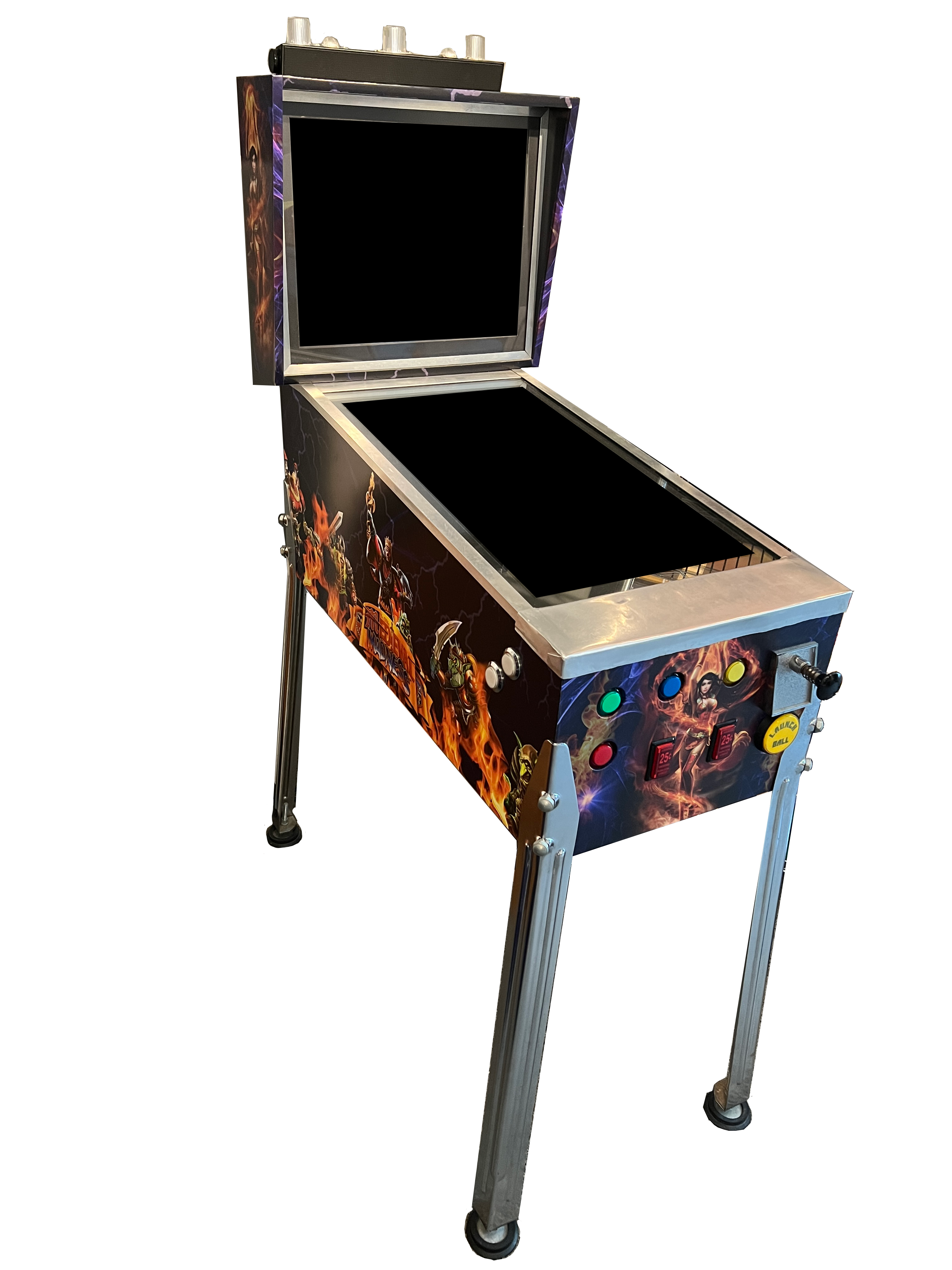
The hardware is the most obvious part of the build. It is a combination of arcade buttons and lights, with an electronic plunger driven by an Apple Mac Mini (2020 update: an old Apple MacPro - Trash Can). It’s all assembled inside a custom built playfield box and back box with two monitors (one for the playfield and one for the backglass display). High brightness LEDs used for flashers lend to the arcade feel, but it’s the physical force feedback provided solenoids are the real pinnacle of the design.
Playfield and Backbox
The carcass of the pinball machine was, as you would suspect, a woodworking project. While it’s just a box, that box has sloped sides, needs mounting for the backbox and legs, and has a few quirky angles to it.
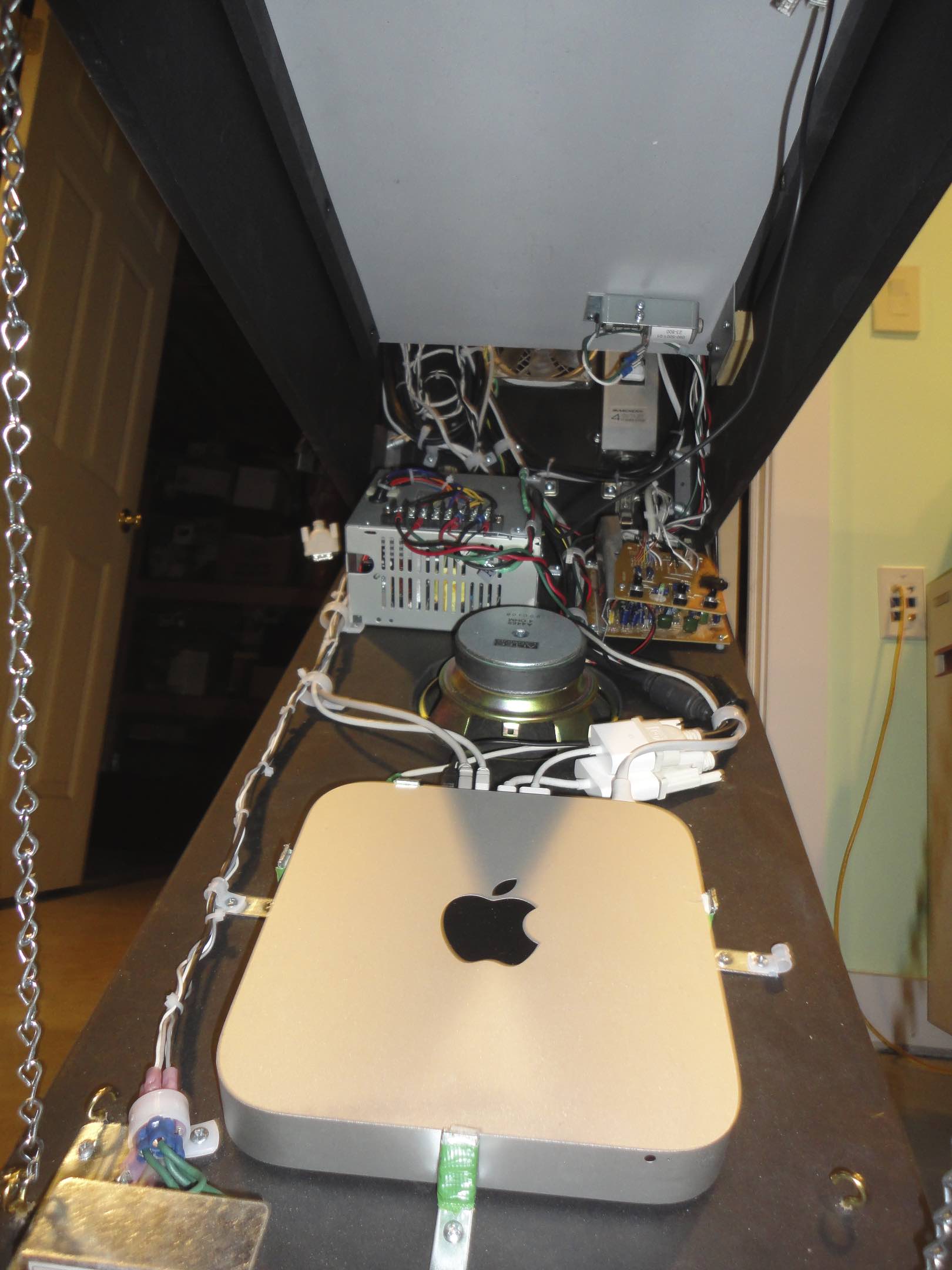
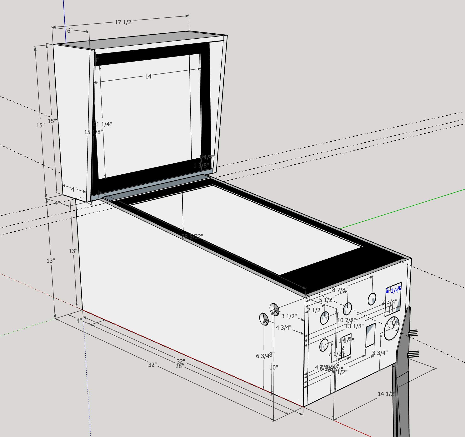 The main design parameter was where and how the computer, solenoids, knocker, control panels, speakers, power supply, and all the wires were going to go. Not to mention if the computer and components generated heat, where was that going to go?
The box has three levels; the lower, mid, and display. The lower level hinges downward and holds the power supply, computer, audio amplifier, and the coin door controls for the pinball table. The mid layer holds the solenoids, control boards, relays, and wiring tie points. There’s also a few speakers here. The display layer holds the playfield display. There are “raceways” in the front and back for wires to go among levels. In the back, where power comes in, I also added a 12V computer fan to draw air through the cabinet and out the back.
The backbox holds the backglass display as well as wiring for the “topper” LEDs and speakers. The speakers were repurposed from the playfield display. It turns out the dell spekaer bar that connects to the display was the perfect size and shape for the topper. I was able to keep the speakers and just rewire them. I stripped out the other components and made room to wire the high power LEDs for the topper; 2 white and 3 RGB ones.
Computer
There are a number of choices for the core computer of a virtual pinball cabinet, and the key component is the display adapter. While more is always better, I was able to get acceptable results with a Mid 2011 Late 2012 Apple Mac mini and it’s Inel HD Graphics 4000. I used the mini for two key reasons;
- It’s small size and ability to fit in my smaller sized cabinet
- I had one on hand that I could use, e.g. nothing to buy.
Here are the specs of the Mac mini (Late 2012)
- 1.4in x 7.7in x 7.7in, weiging in at 2.7lbs
- 2.5 GHz dial core Intel Core i7 (Turbo Boost up to 3.3GHz) with 6MB L3 cache
- 250GB Solid-state Drive
- Intel HD Graphics 4000
- 8GB 1600MHz DDR3 memory
- Support for two displays at 2560x1600 at millions of colors (HDMI, Mini DisplayPort)
- Audio line out/headphone minijack
- 4 x USB 3 ports
- Gigabit Ethernet, 802.11n/a/b/g Wi-Fi wireless
- Bluetooth 4.0
[2020] In 2020 (approximate) the Mac Mini was replaced with an old Apple MacPro “trash can”. While it’s still an old computer it has discrete graphics cards and seems to handle the load a little better than the mini. Unfortunately, it gets a lot hotter than the mini and pretty much any other computer I’ve ever used. I’m paying close attention to the temps.
Displays
One of the keys to an immersive experience is the pair of displays; one for the playfield and one for the active backglass. The only critical feature when choosing the displays was that they automatically powered on when power was applied. There’s no easy way to open the case and push a power switch. So if they don’t auto-power on they will be unusable for the project.
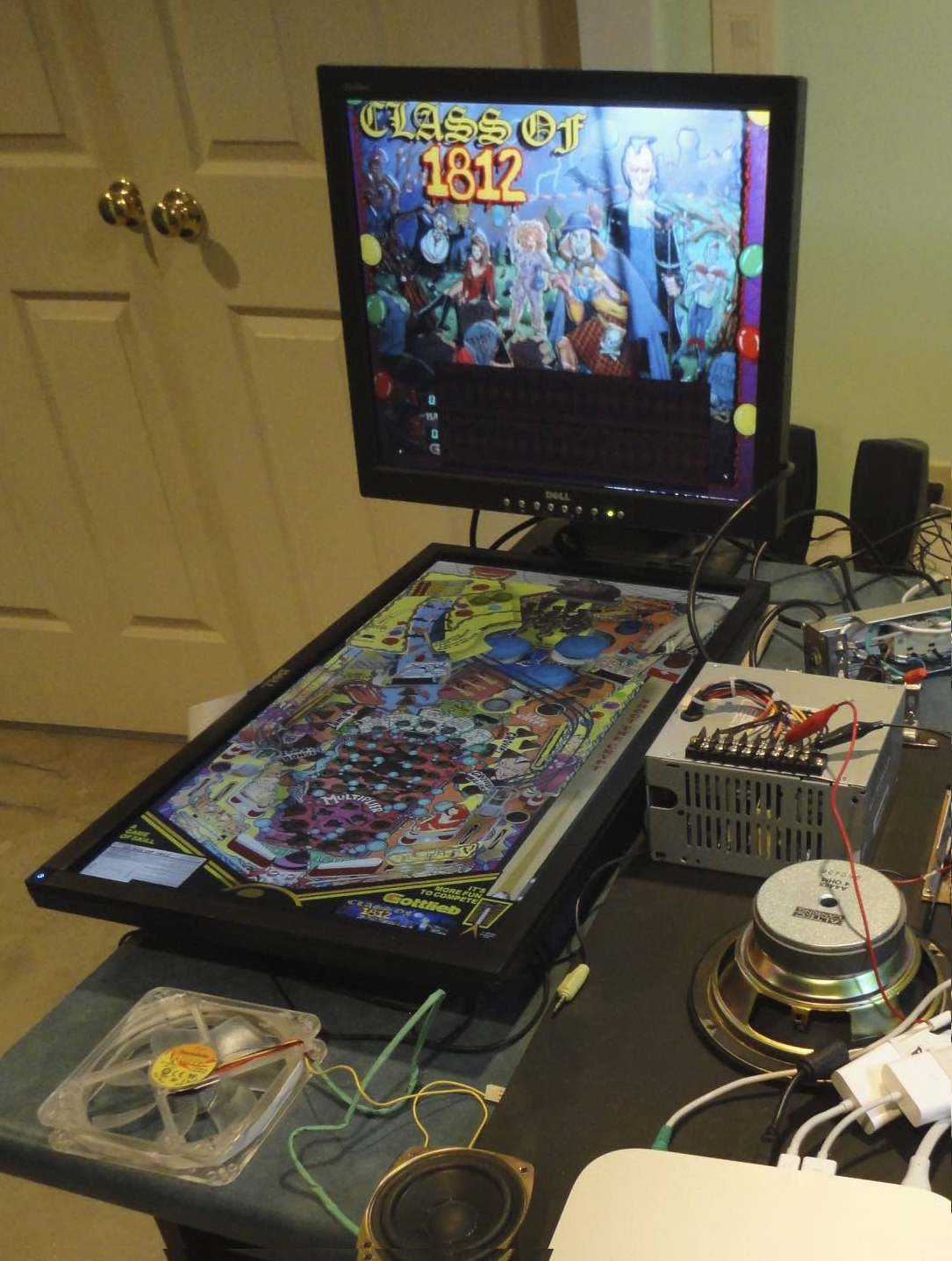 The playfield is perhaps the most important. It’s a widescreen (16:9) display that lays down into the cabinet in portrait orientation. Within the virtual pinball community there are a number of opinions about which monitors are the best. There’s also a number of folk running 4k displays. I was working with what I had, so a 1080p 24” was it.Unfortunately, the display is not great viewing at some off angles, so at some point a better display might be in order. This is really a problem for people who are watching. In landscape orientation you cannot view the monitor from below. When put in portrait orientation it makes one side (left or right) unusable for people to watch you play.
The backglass isn’t anything special. I used a 15” 4:3 aspect ratio monitor. On this display, will be the backglass from the pinball table and any score reels or “DMD” display. This was a really old monitor. The backbox is just barely thick enough to hold it and the wires for the LED topper. I opened up a few extra large vent holes on the back side near the top to help address any heat problems. Turns out I used them for some wires as well.
Electronics
There’s a fair amount to the electronics in the Minipin beyond the computer. To drive most of them I used an old PC power supply. It worked out well as it provided 5V and 12V and has plenty of juice (watts) to run the higher power components like car starter solenoids and high power LEDs.
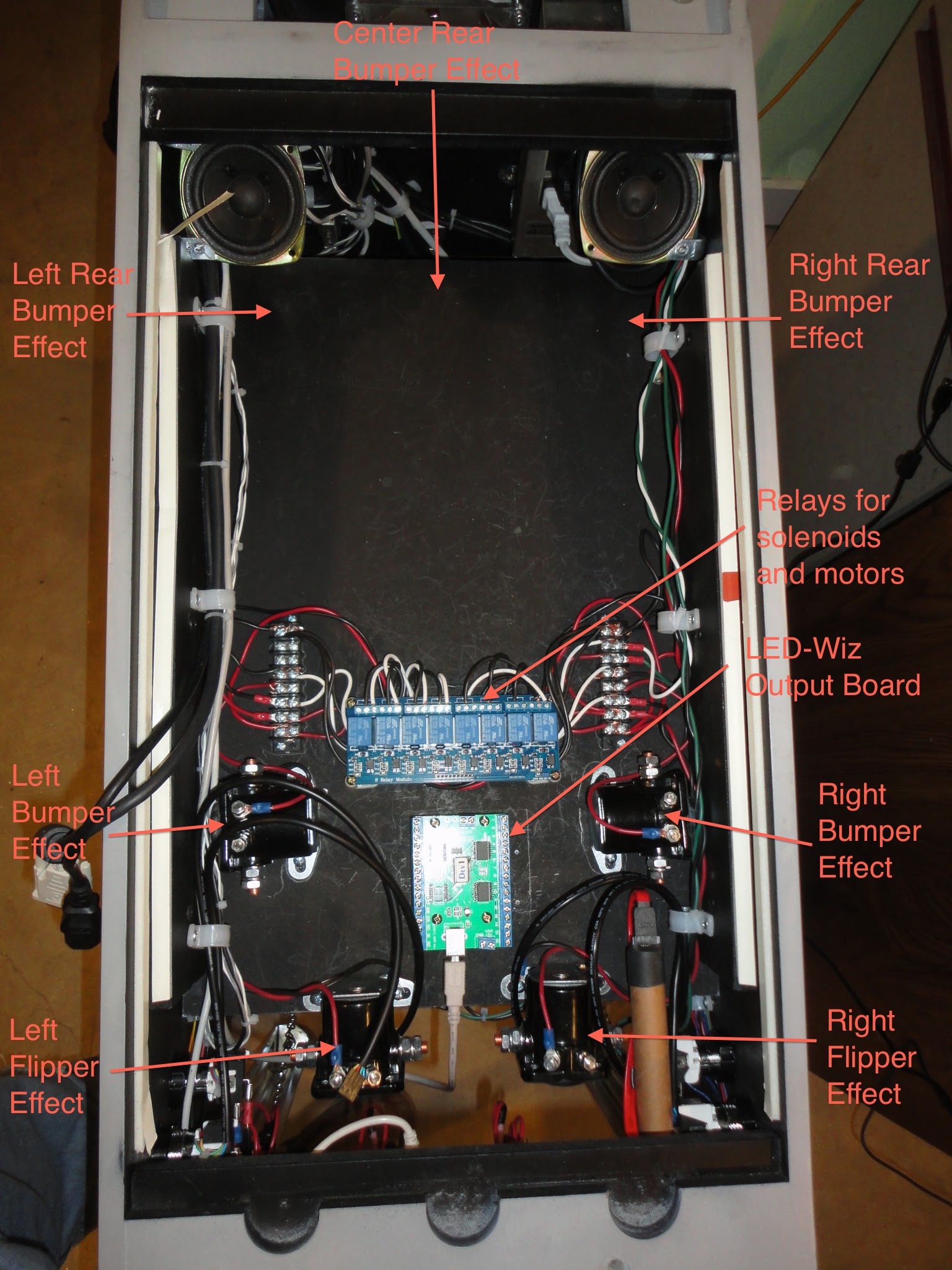
There are two main interface components, a Pinball Wizard controller and an LEDWiz controller. The Pinball Wizard is used mostly for input and the LEDWiz for output. Pretty much everything is wired to one of these two controller boards. There are two relay boards as well, but these are controlled by the LEDWiz to isolate the high power (12V) components from the low power (5V) of USB and the computer.
The Pinball Wizard was custom built to manage the input related to a virtual pinball machine. It connects via USB to the computer. On the other end, it has connections for arcade buttons and switches. Most importantly it has a connection for a plunger and an accelerometer. The plunger connection and custom plunger senses the position of the plunger and reports so you can launch the ball with varying strength. The accelerometer input is integrated as a game controller and can allow nudging and tilt-sensing within a pinball table. I’ve not gotten the accelerometer to ever completely work. It’s either too sensitive or I just cannot get the mouting orientation correct. In addition, the board connections are weak at best. I’ve had to resolder the plunger connection a few times.
The LEDWiz is used to control all the solenoids, LEDs, knockers, etc. in the cabinet. The 12V components (and some of the 5V ones) are connected via a relay board to isolate things and keep the magic smoke from escaping. The LEDWiz has 32 ports but I’ve found that’s barely enough for what I’ve put in there and have planned for the future. The outputs are controlled from within a pinball table via the Direct Output Framework. Fortuantely there’s a relatively easy to use configuration program the DOF Configtool. While it’s not perfect, it creates the appropriate configuration based on where things are wired. Most pinball tables I’ve come across have their play elements entered into the DOF database, so you don’t need to configure them manually any longer.
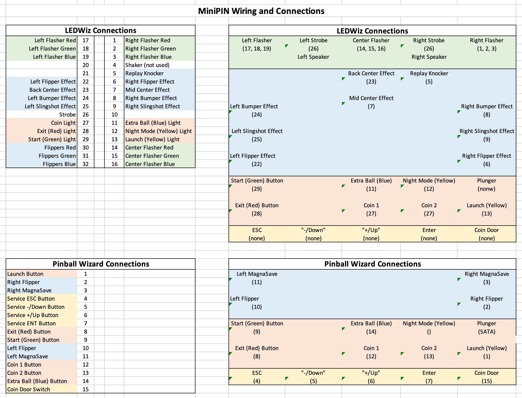
You can see from the above wiring and configuration there are a number of outputs. I won’t go into detail on each individual one. Besides, this list will likely be out of date when you read this.
The one thing I will point out is the use of car starter solenoids for haptic feedback. This is one of the truly fun elements of the build. The solenoids, when triggered give a nice solit thunk, just like the electro-mechanical elements inside a real pinball machine. These make it actually feel like there are mechanical compoents inside the box! When the ball hits a target, you get physical and audible feedback as if a real solenoid was triggered to eject or bounce the ball around on a real playfield.
Software
The entire project is focused around Visual Pinball and Visual PinMAME. These two programs, used together, are what make this project a reality. They both run on Microsoft Windows (Windows 10 at this time). There are also a number of add ons that work with one or both of these programs to make a seamless, realistic system.
Visual PinMAME is responsible for emulating Read Only Memory (ROM) dumps of real pinball machines. PinMAME however is not very useful by itself. Visual Pinball the more visual part of the system. In Visual Pinball table creators can graphically design what the pinball table looks like and all the toys and gadgets that appear on the playfield. Using these, it emulates the physics of the ball rolling around. When it interacts with a plyfield element, it passes this along to PinMAME which then updates the internal state of the machine. Visual Pinball can then read the status of lights, bumpers, etc. from that state and then reflect it in the GUI.
Visual Pinball also can use a third-party add-on to display the backbox screen, called the backglass. This happens via a Windows DLL call. Smart developers in the pinball community have figured out that they can intercept these calls and control other devices based on what’s going on. This is where the Direct Output Framework and active backglasses come into play. They intercept the calls and trigger real devices via the LED Wiz.
While Visual Pinball can control and play a pinball table, it does not have a way to show what tables are installed, nor select among them, other than using a Windows “File… Open” dialog. This is where a front end comes in, namely PinballY.
PinballY is loaded at Windows startup. It is an interface designed to be used by the flipper and start buttons. It displays the installed pinball tables and allows you to select and start playing, via Visual Pinball, any of them. There’s also a ton of additional configuration and menu manipulation available and a JavaScript scripting layer for advanced customization and custom add-ons.
Conclusion
While I haven’t documented everything here, hopefully it’s enough to describe the overall project and some of the highlights. Frankly, it’s just been years since I built it and so much has changed. Perhaps I’ll get around to updating this with those changes. In the meantime, keep playing!