Big Brother Traffic Light
in
Network Operations Centers and Help Desks all over monitor their systems and networks with an open source product called Big Brother – the freely available version is now Hobbit. Here’s how to add a traffic light to indicate network status.
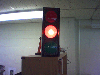
Big Brother provides a web interface that shows the status of the network, and systems. The web interface allows you to drill down and see the status of any device monitored. It does all this in a very simple and elegant way, by providing color indications, red, yellow, and green to tell you how things are going. Well all of this really can put the idea of traffic lights into your head if you like to “re-purpose” consumer electronics like I do. So lets get to task and use our desktop computer, running Java to monitor a BigBrother web page and change a faux traffic light to match the color-status of our network.
Project Details
The project makes use of the “OneWire” protocol and chips from Dallas Semiconductor. These easily interface with RS-232 or USB “host” controllers and even microcontrollers, like the PIC, AVR, and Basic Stamps. As described here, this project ends up being a little pricey. So consider it a proof of concept that we can later work into a much cheaper product. [This is the case with a home-made PC board and a $2 Dallas Semiconductor DS2408 chip to be covered in the future in the MiniStopLight project]
The components that we will be working with include:
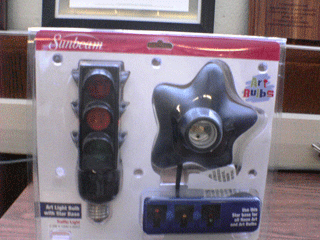
Faux Stop Light $20 from Spencer Gifts. This stop light is almost perfect for our needs. It has 120V AC night-light bulbs, 12V DC would be preferred so they could be powered the relay board without needing a power supply. Unfortunately the lights blink, actually the bulbs have the blinking built-in. We don’t want blinking lights! Fortunately the bulbs can easily be replaced with standard night-light bulbs from the local grocery/hardware store.
OneWire Relay Board $69 from AAG Electronica This board is rather expensive for the project, but I had one on hand. After all, prototypes are not known for being cheap! The relay board connects to a “OneWire bus” and requires a 12V DC power supply to drive its 220V capable relays. There are four (4) relays and four (4) inputs on the board. This project only used the relays. Three (3) lights and one (1) buzzer - yes there is a buzzer. The board is built around a Dallas Semiconductor DS2408 8 way addressable switch.
Wall Wart and Telephone Jacks $10-$15 (maybe), these might be in a well-stocked junk box These are more or less in the miscellaneous parts section. 12V DC “wall wart” power supplies are easily found, as are old telephone jacks, and a 12V buzzer could always be gotten at RadioShack. As well as wire, how could you live without a pile of wire at your house I’ll never know.
Software $0 from my own brain. So the software is free I am a software developer after all! The code is very simple. In fact if you were to put another DS2408 chip on the OneWire bus, it would think it was another stop light!
Build Steps
- Dremel out the traffic light case to accept telephone jacks
- Install the OneWire relay board, rewire lights, add a buzzer
- Tear apart and re-use a walwart to get 12V from 120V
- Put the light back together and replace blinking lights
- Hook-er-up and write some code to make-er-go
Construction
Traffic Light Case Modifications:
We want the traffic light to look professional, so to the Dremel tool!
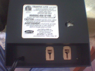
In the photo you can see an opening cut into the traffic light case to mount some old-school 4-wire telephone jacks. I had these laying about so ones that you purchase will be different. Levitron has some jacks that you can buy, designed for their home systems that should work very well. They snap-in to wall face plates. Also, in retrospect, we maybe should use cat-5 8-wire jacks for compatibility with some other off-the-shelf one wire products.
Here we can see how the telephone jacks are mounted from the inside. They snap-in cleanly, but I added a touch of hot melt glue just in case. The battery and relay board you see in this photo are the next step, lets get to it!
Update Electronics:
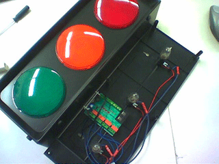
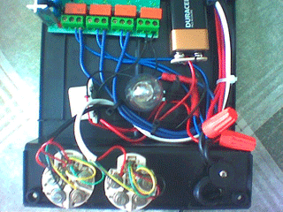
The first issue to attack was where to place the OneWire relay board. This photo shows it close to where the phone jacks will be (at the bottom). The best placement seems to be between the green and yellow lights. A bit of double sided tape and/or a wire-tie holds it in place.
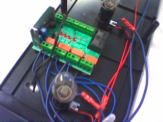
Here’s a closer view of the placement and the beginning of rewiring.
The rewiring is rather easy. Each light was originally wired from the power cord (directly). We simply need to insert a relay inline with each light. So, snip one wire from each light and replace it with a wire from one relay. And take the other end (from the power cord) and bring it to the other relay connection. Viola, relays wired. The AAG Electronica OneWire relay board makes all these connections very easy with screw terminals.
Modify Power Supply:
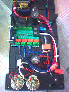
Perhaps the most difficult hardware modification is getting 12V to the relay board. To do this, we scavenge an old wall-wart style power supply that puts out 12V. Dremel apart the case so we can get to all the internals. We need to connect the 110VAC side of the transformer to our 110V power cord, same place we connected the relays and light. The 12V side goes to the power in, again screw terminals on the relay board. In the photo below, the red wires from the transformer (top) go to the red wire nuts for 110V. The black wires go to the relay board’s power input. Here a wire-tie is needed to hold the transformer in place, its relatively heavy.
Lastly, using one “phone” cord cut in half, the OneWire bus is brought from the relay board to the phone jacks on the traffic light. Simply lop a phone cord in half, plug in the RJ45 on the relay board. On the other end, match the color coded phone cord to the color coded terminals on the phone jack.
The relay board has four (4) relays and we only need three (3) for the lights. So we can use the fourth relay to control a buzzer. In the photo above, the buzzer is hooked to a 9V battery because it is a 9V buzzer. If you have, or get, a 12V buzzer, you could wire it using the same relay board 12V supply. I’m cheap so I used what I had on hand.
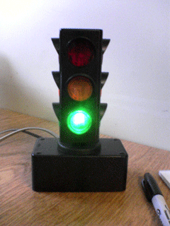
Reassemble Traffic Light:
During re-assembly remember to clean up the wiring with wire ties to keep things looking nice. People will want to see the guts of your project, not just the outside. Make sure everything is secured so it does not rattle around when you move the light. With the light used here, remember to replace the stock blinking lights with non-blinking 4W or 7W night lights.
Monitoring Software:
The software to control the light can be a simple or complex as you like. Dallas Semiconductor provides a development kit for OneWire on their web site. The Java version is, as expected, the most portable. It provides Java objects that correspond to the computer adapter and each device on the bus. The device in the relay board is a DS2408 8-port switch. So our software task is to find out which ports control which light and then write code to monitor our BigBrother web page, scape it’s status and turn on the correct light.
This section is incomplete… I need to post my code
Future Traffic Light Work
One “problem” is that the software opens and holds the One Wire bus. This makes it not a very polite system if there are others that need access.
Another problem, as noted earlier, is that the software does not look for a specific DS2408 switch, it just looks for all of them and treats them all as if they are the target (stop light). Identifying the correct switch would also let it coexist with other devices - like the One Wire weather station.
I’ve also built a “desktop” version of the traffic light. This version uses a custom PC board and the DS2408 chip, without the expensive OneWire Relay Board from AAG. Of course, it’s another repurposed toy. This one was from Wally-world for $10.00 if I recall correctly. I’ll get the schematics and details up soon, I hope.
Why did I do this?
Because it seemed like fun.
Woot!
![]()
January 20, 2006: The Big Brother Taffic Light appeared on Make’s website!